Potentiometers are key components in many electronic devices, serving as variable resistors to manage voltage and current. From volume adjustments in speakers to brightness tweaks on lightbulbs, potentiometers play a pivotal role in everyday gadgets - but knowing their pinout and diagnosing common faults can make all the difference when working on projects or repairs for electronic devices.
This guide focuses on potentiometer pinouts and how to troubleshoot common faults and repair them.
Understanding Potentiometer Pinouts: The Basics of Pin Configuration
A potentiometer, commonly called a "pot," is a three-terminal component that regulates circuit resistance. Each pot's three terminals allow it to adjust voltage, which ultimately controls parameters such as volume or light intensity.
A basic three-terminal potentiometer connects one terminal to a reference voltage, and the wiper at terminal two provides variable output. It connects its third terminal directly to the ground or another voltage level. This simple configuration forms the heart of the operation.
also read:
Rotary Potentiometer Pinout Explained: How to Adjust Resistance
- Pin 1 (Fixed End): This terminal connects with one end of the resistive track. It is usually attached to either positive or ground voltage sources.
- Pin 2 (Wiper): The wiper is the adjustable middle pin of a potentiometer. Adjusting or moving it around the resistive track changes the resistance between terminals 1 and 2, altering output voltage levels accordingly.
- Pin 3 (Fixed End): Much like Pin 1, this terminal connects with the other end of a resistive track, usually connected with either fixed voltage or ground.
Potentiometers feature three pins that work harmoniously to enable precise control over output voltage, making them essential components in devices requiring adjustments.
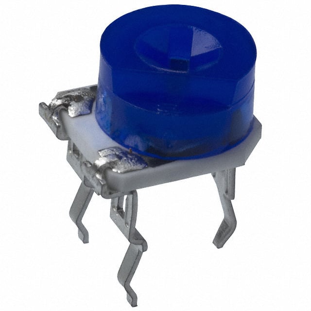
Rotary Potentiometer Pinout Explained: How to Adjust Resistance Rotary potentiometers feature an adjustable shaft that makes adjustments. However, all three-pin potentiometers follow a similar layout regarding how their pins connect and how users interact with them.
Looking at a potentiometer with its shaft facing upwards and terminals facing towards you, its pins tend to function in this manner:
Pin 1 (CCW or Counterclockwise Terminal): Connected to one end of the resistive track.
Pin 2 (Wiper Terminal): This pin can be adjusted in the middle to take out the output voltage.
Pin 3 (CW or Clockwise Terminal): This pin connects with the other end of a resistive track, typically to supply voltage.
A rotary potentiometer's greatest strength lies in its versatility. By switching Pin 1 and Pin 3, you can quickly switch the direction of resistance adjustment. For volume control applications, this could mean turning the knob clockwise can either increase or decrease volume depending on how the terminals are wired.
Linear Potentiometer Pinout for Smooth Adjustability
A linear potentiometer (also called a slider) features a similar construction as its rotary counterpart; instead of the rotating shaft, its primary element consists of a sliding mechanism. These potentiometers are widely used in audio sliders, light dimmers, and other gradual adjustment applications.
- Pin 1: Connected to VCC (positive supply voltage).
- Pin 2 (Wiper): The slider contact that controls resistance adjustment.
- Pin 3: Connected to the ground (GND).
Linear potentiometers are perfect for applications requiring precise and easily controllable sliding adjustments, such as audio equipment or dimmer switches.
Digital Potentiometer Pinout and Electronic Adjustments
Unlike their analogue counterparts, digital potentiometers adjust resistance using digital signals such as I2C or SPI. As such, they offer greater flexibility and precision, making them the ideal choice for microcontroller projects or embedded systems.
Digital potentiometers typically feature more pins than their analogue counterparts to accommodate digital communication interfaces, and here is a breakdown of standard pins:
Power Pins (VCC, GND): Provide power to the IC for its operation.
Potentiometer Pins (RH/VH, RL/VL, and RW/VW) Correspond to the analogue potentiometer's high-end, low-end, and wiper terminals, respectively.
Control Interface Pins (SPI/I2C): Pins are designed to enable digital control of the wiper position using digital protocols such as SPI or I2C.
Shutdown Pin (SHDN): Used to set the potentiometer into low-power mode when not in use.
Wiper Bias Pin (V+): Some models include an internal MOSFET biasing pin for biasing purposes.
Digital potentiometers can be particularly helpful when precise and programmable controls are essential in your projects yet require careful wiring and configuration for smooth functionality. However, optimal communication between the potentiometer and controller must be ensured.
Common Potentiometer Pinout Faults and How to Correct Them

The Potentiometer Won't Adjust Properly
If your potentiometer doesn't adjust as expected - whether it is difficult to turn or slide or there is no noticeable change in output - it may be due to dust, dirt or wear on its resistive track.
The first step to solving potentiometer issues is cleaning it thoroughly using contact cleaner or isopropyl alcohol, such as in a contact cleaner bottle. Older or overworked potentiometers may have internal wear affecting their resistive track, leading to problems. If cleaning doesn't resolve this, replacing is likely best, especially with older electronic equipment or devices which require frequent adjustments.
No Voltage Output
An especially annoying issue arises when there is no output voltage from Pin 2 of your wiper pin (Pin 2). This could occur if your potentiometer has improper connections or an internal failure.
First, check the wiring to ensure Pins 1 and 3 are correctly connected to their respective voltages (Pin 1 should be connected positively; Pin 3 to ground). Furthermore, double-check that Pin 2's wiper makes contact with the resistive track and moves smoothly. If there is still no voltage output from your potentiometers, replacing them is likely your most straightforward option.
For digital potentiometers, ensure your control interface (e.g. I2C or SPI) is working as expected, as any disruptions here could lead to no output at all.
Noisy Output or Intermittent Adjustment
Potentiometers that produce noisy or fluctuating output (such as crackling sounds when adjusting) often indicate wear or dirt build-up inside their components, especially those used in audio equipment such as rotary potentiometers. This issue typically manifests in audio rotary potentiometers.
To address this, start by cleaning the potentiometer. Apply a small amount of contact cleaner to its moving parts to remove dust or debris preventing the wiper from moving smoothly. If this doesn't do the trick and the noise continues, your internal resistive track may have worn away; replacement would be best.
Digital Potentiometer Not Responding
When using a digital potentiometer, its wiper may fail to adjust correctly or respond. This could be caused by issues with its digital control interface (I2C/SPI), incorrect wiring or poor software communication; all factors must be carefully considered before determining the problem.
Inspect the physical wiring connections, particularly those for I2C (SDA, SCL) or SPI (MISO, MOSI, SCLK). Ensure your microcontroller with its power pins (VCC and GND) is correctly configured for the potentiometer. Verify that software correctly addresses it via I2C or SPI address addressing mechanism; if nothing seems amiss but the potentiometer still fails to respond, then replacement may be required as components may have failed.
Potentiometer Adjustments Are Reversed
In certain circumstances, potentiometer adjustments might need to be reversed in specific directions—turning clockwise may decrease voltage, while turning counterclockwise may increase it.
This issue could be due to how the potentiometer is connected to the circuit. Still, a straightforward solution lies in swapping Pins 1 and 3 together. This will reverse the potentiometer's resistance adjustment direction, so turning clockwise increases the voltage. At the same time, turning counterclockwise decreases it, which is helpful for audio equipment volume control applications.
Potentiometer Showing Unexpected Resistance
Sometimes, a potentiometer might show unexpected resistance readings even though it's in good working condition; a malfunctioning resistive track or poor connection issues may cause this.
To diagnose this issue, measure the resistance between Pins 1 and 2 (across the wiper) and Pins 2 and 3 (on either end of the resistive track). Suppose there are discrepancies or errors between resistance values measured between Pins 1-3 (crossing over) and Pins 2-3 (along the opposite end). In that case, cleaning may help, but if that does not restore proper functionality, replacing will.
Finding Pinouts in Datasheets: The Proven Way To Accuracy
Always refer to the potentiometer's datasheet for accurate and specific pinout information. Datasheets provide extensive diagrams and pin descriptions, including their exact locations and functions; when purchasing potentiometers from different manufacturers, it is wise to verify whether their pinout may differ slightly in configuration.
Essential Potentiometer Pinout Tips
Potentiometers typically label their pins with numbers or functions (e.g. "Wiper", "Terminal 1", and "CCW" for rotary types)
Check for markings on the potentiometer's body, such as resistance values or taper types ("A" for audio taper and "B" for linear taper).
Be mindful of package type (DIP, SOIC, etc.), which can impact pin layout.
Conclusion:
Whether it is for a DIY electronics project or repair on an existing device, understanding potentiometer pinouts and issues is invaluable. Knowing each function of each pin will allow you to integrate potentiometers seamlessly into circuits while troubleshooting common problems quickly and effectively. Consult the datasheet for the most precise information possible. Don't be shy about replacing faulty potentiometers to keep your device functional function.